ELECTRONICS & CONTROL INTERFACES

Custom Silicone Components for Electronics & Control Interfaces

Electronic products often require the silicone component, visible controls and surrounding enclosure to be reviewed together. SM supports drawing- and sample-led projects for custom silicone keypads, molded buttons and related interface components.

Device Layout • Housing Fit • Visible Markings • Component Integration

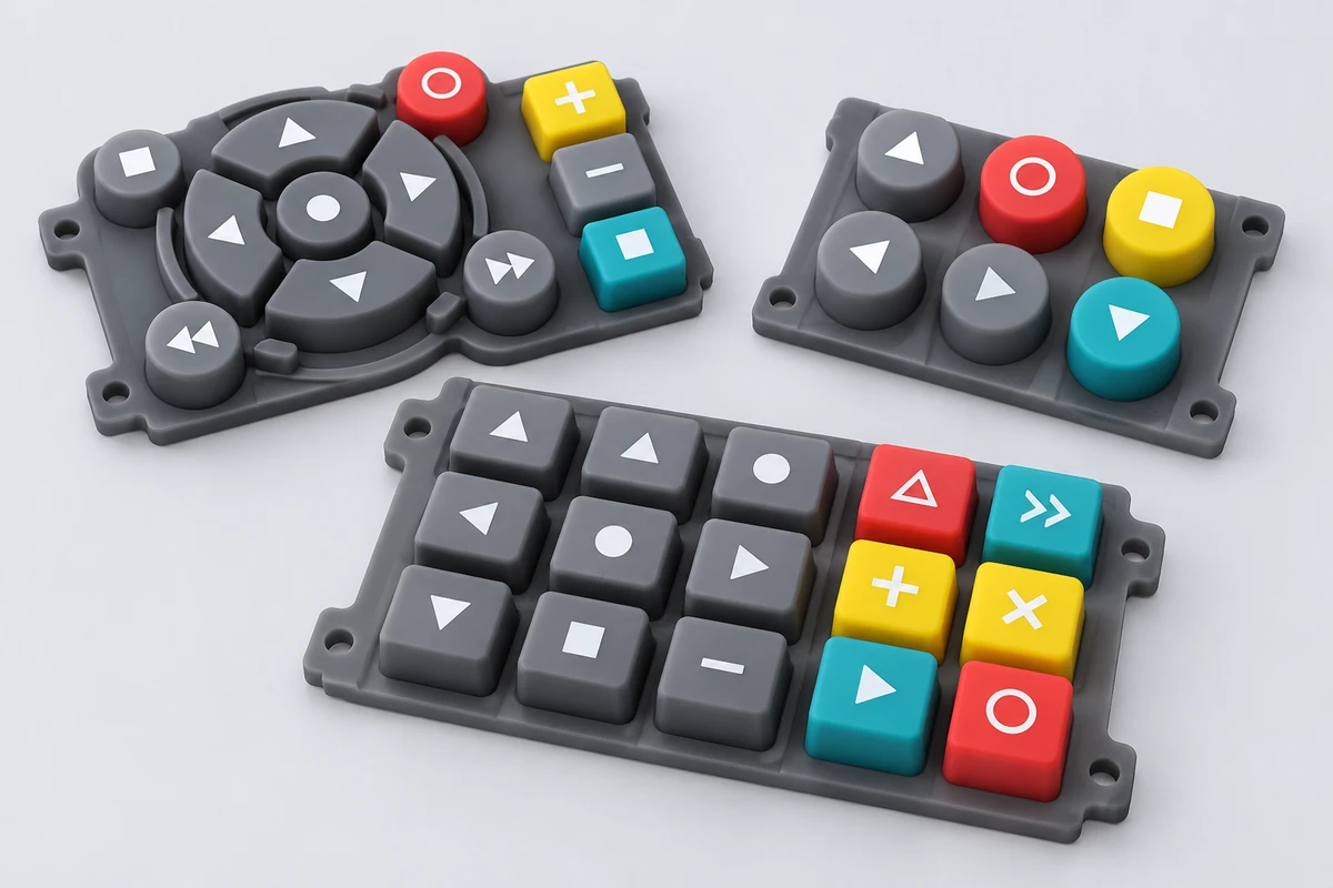
AI-assisted illustration of molded silicone keypad mats with colored control keys
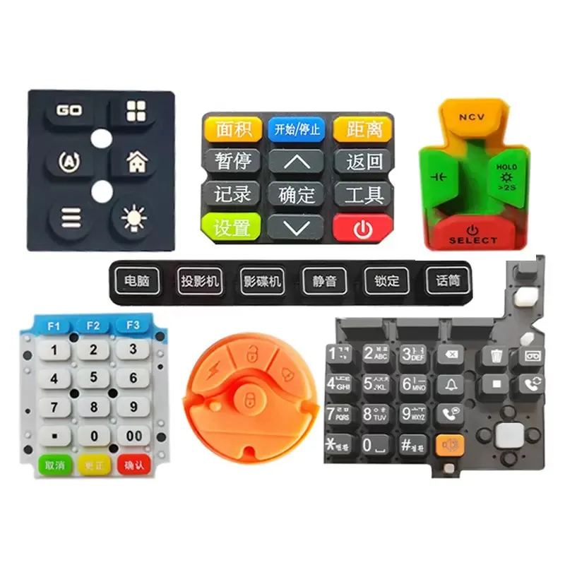
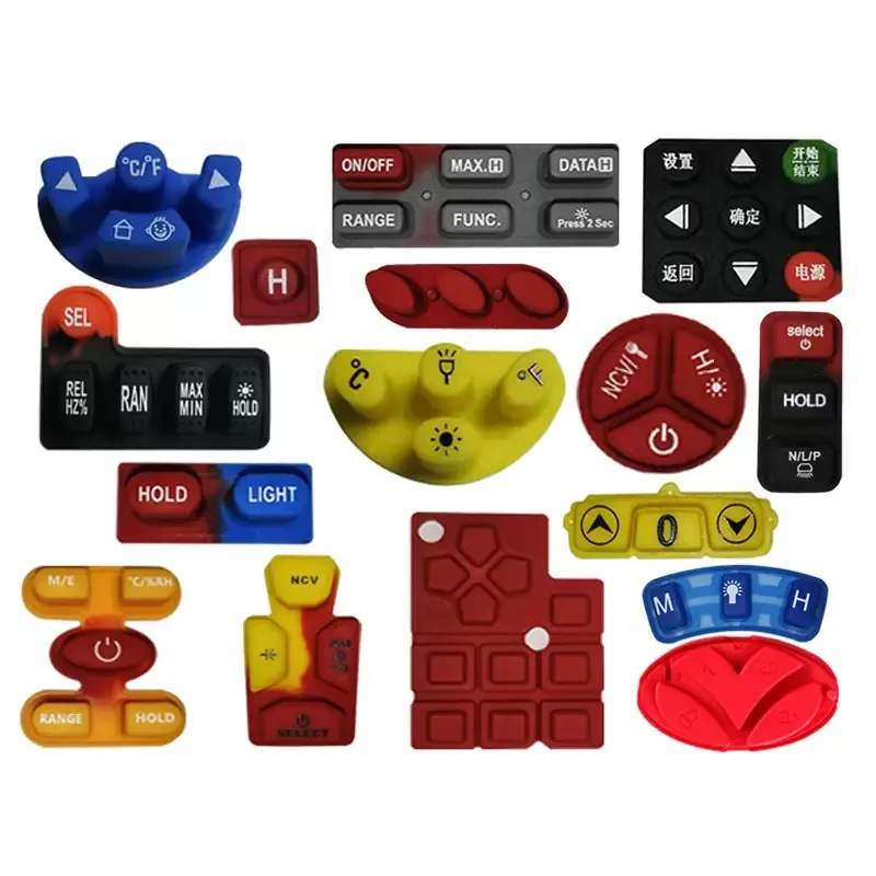
Assorted custom silicone keypad and button components
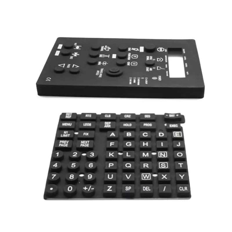
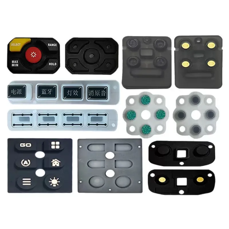
Black custom silicone keypad components for control interfaces

COMPONENT DIRECTIONS

Silicone Buttons, Keypads and Interface Components by Product Role

The finished device may use one molded keypad, individual buttons or several related interface parts. Start with the component role that best matches the current design.

01

Custom Silicone Keypads

Multi-key molded components developed around the required layout, geometry and relationship with the surrounding product.

02

Molded Buttons & Button Mats

Individual, grouped or connected button structures for product-specific control areas.

03

Printed & Marked Keys

User-facing components where approved legends, symbols, colors or graphic areas form part of the visible interface.

04

Silicone + Plastic Interface Parts

Related silicone and plastic keys, covers or housings that need to be reviewed as part of one product interface.

05

Covers, Pads & Interface Pieces

Custom molded silicone parts used around controls, openings, touch areas or other product-specific interface locations.

06

Drawing- or Sample-Led Custom Parts

Existing samples, assembled products and CAD data can provide the starting point for unusual or replacement component structures.

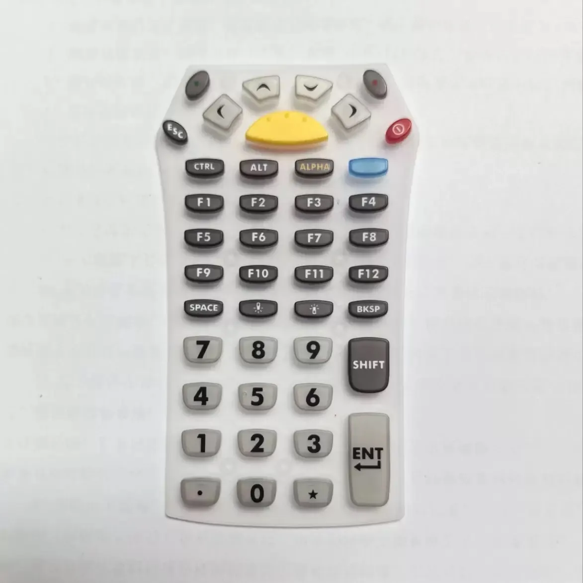
Large custom silicone control keypad with numeric and function keys

DEVICE INTERFACE

Design the Silicone Interface Around the Housing, Panel and PCB

A usable control interface depends on more than the silicone part alone. The first review should identify the neighboring parts and buyer-defined requirements that control fit, appearance and operation.

Layout & Control Arrangement

Define key count, spacing, grouping and the overall user-input arrangement.

Housing, Bezel & Panel Fit

Show how the component sits in the enclosure, bezel or panel and where alignment or compression matters.

PCB / Contact Concept

Provide the intended contact or switch relationship as a buyer-defined project input where it affects component structure.

Legends & Visible Surfaces

Identify approved symbols, artwork, colors and user-facing surfaces that must be coordinated with molded geometry.

Plastic Keys & Neighboring Parts

Include related keycaps, covers, supports or mating components when they influence the silicone part.

Assembly & Sample Context

Use an assembled-product reference or physical sample to clarify alignment, movement and acceptance priorities where available.

Project note: Tactile response, electrical properties, lifecycle, sealing and environmental performance are project-specific requirements. They must be defined and confirmed for the individual design.

COMMON PRODUCT CONTEXTS

Electronic Products That Use Custom Silicone Control Components

Product formats vary, but the component review remains focused on layout, fit, visible requirements and relationships with neighboring parts.

Remote Controls & Handheld Devices

Compact keypad and button components developed around handheld layouts, enclosure geometry and visible control areas.

COMPACT INTERFACES

Industrial Controls & HMI Equipment

Molded silicone components for control panels reviewed around panel fit, key arrangement, markings and the surrounding equipment interface.

CONTROL PANELS

Consumer Electronics

Custom silicone buttons and related interface parts developed around compact housings, visible appearance and assembled-product fit.

DEVICE CONTROLS

Home Appliances & Smart-Home Controls

On-device buttons and keypads reviewed around front-panel geometry, symbols, color areas and housing relationships.

ON-DEVICE INPUT

POS Terminals & Access-Control Equipment

Numeric and function-key interfaces developed around layout, legends, enclosure fit and project-specific inspection priorities.

KEY INTERFACES

PROJECT REVIEW INPUTS

What to Send for a Silicone Interface Project Review

The first project brief does not need to be complete. Send the information already available and identify what still needs to be defined.

01

Component files

2D drawing • 3D / STEP file • physical sample • existing component reference

02

Device context

housing, bezel or panel data • mating parts • PCB relationship • assembled-product image or sample

03

Visible requirements

legends • symbols • colors • artwork • user-facing surfaces

04

Functional inputs

buyer-defined contact method • tactile/performance targets • use environment where relevant

05

Critical dimensions

fit points • alignment • openings • movement • tolerance priorities

06

Commercial context

estimated quantity • project stage • sample expectations • required documents

SM reviews the available project information before the applicable tooling, sampling and manufacturing route is confirmed.

RELEVANT PRODUCT ROUTES

Choose the Product Route Closest to Your Component

Silicone Keypads & Buttons

For multi-key keypads, molded buttons, button mats, visible legends and keypad-specific engineering inputs.

Industrial Silicone Parts

For functional molded components such as boots, grommets, seals, bushings or protective parts.

Broader Product Categories

For consumer, household, personal-care, pet, baby or other silicone product categories.

FROM REQUIREMENTS TO MANUFACTURING

From Interface Requirements to Tooling, Molding and Finishing

Once the product relationship is understood, the project can move into the manufacturing decisions relevant to the actual component.

Tooling & Silicone Molding

Review component geometry, tooling direction and the silicone molding route against the approved design.

Plastic & Interface Integration

Where related plastic keys, covers or housings are included, review how the components fit together.

Marking & Surface Finishing

Coordinate approved printing, laser engraving, color areas or other finishing requirements with the molded surface.

Assembly & Inspection

Define sample configuration and the fit, appearance, dimensions or other project-specific points to be checked.

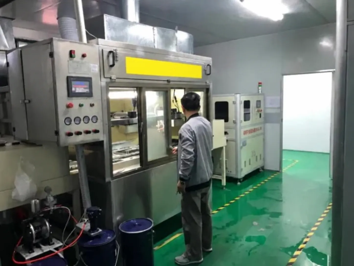
Mold tooling and CNC machining for custom components
Laser engraving equipment for silicone component markings
Inspection and testing workstations for finished components

PRODUCT EVIDENCE & FAQ

Product Evidence and Buyer Questions

Approved SM product images show keypad, button and interface-component directions. Verified manufacturing media connects the project discussion to tooling, molding, finishing and inspection work.

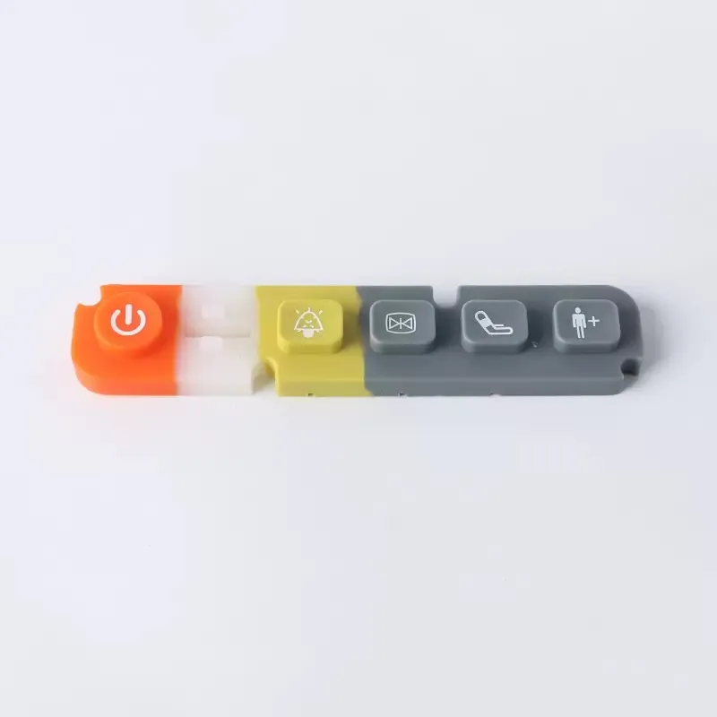
Multi-color molded silicone button strip for a control interface
Assorted custom control keypad and silicone button layouts
Assorted molded silicone buttons and grouped control keys
Yes. An existing component or assembled-product sample can provide a useful starting point for reviewing geometry, visible surfaces and mating relationships.
Include the housing, panel, bezel, PCB relationship or mating-part information where it affects fit, alignment, movement or the contact concept.
Yes. Where related plastic keys, covers or housings are included in the project scope, their relationship with the silicone component can be reviewed together.
Project requirements may include approved legends, symbols, colors and other visible details. The finishing route should be reviewed against the actual molded part and artwork.
Include any buyer-defined targets for contact method, tactile response, lifecycle, environmental exposure, sealing or other functional requirements. These must be reviewed and confirmed for the individual project.
Provide the available component file or sample, related device context, critical fit points, visible requirements, estimated quantity, project stage and any required acceptance documents.
START WITH THE DEVICE INTERFACE

Send Your Electronic Interface Component for Review

Share the drawing, CAD file, physical sample or assembled-product reference already available. Include the housing relationship, visible requirements, critical dimensions and quantity context so the next project steps can be reviewed.