INDUSTRIAL EQUIPMENT
Custom Silicone Components for Industrial Equipment
Custom silicone components for machinery need to fit the assembly, not just the drawing. SM reviews seals, grommets, sleeves, bellows and other molded part projects around mating geometry, installation and buyer-defined operating requirements.
Drawings • Mating Parts • Service Conditions • Sample Requirements

Silicone Component Applications in Industrial Equipment
Connect the part shape to its position in the equipment. These component examples help define the interfaces to review; suitability depends on the actual design and service conditions.
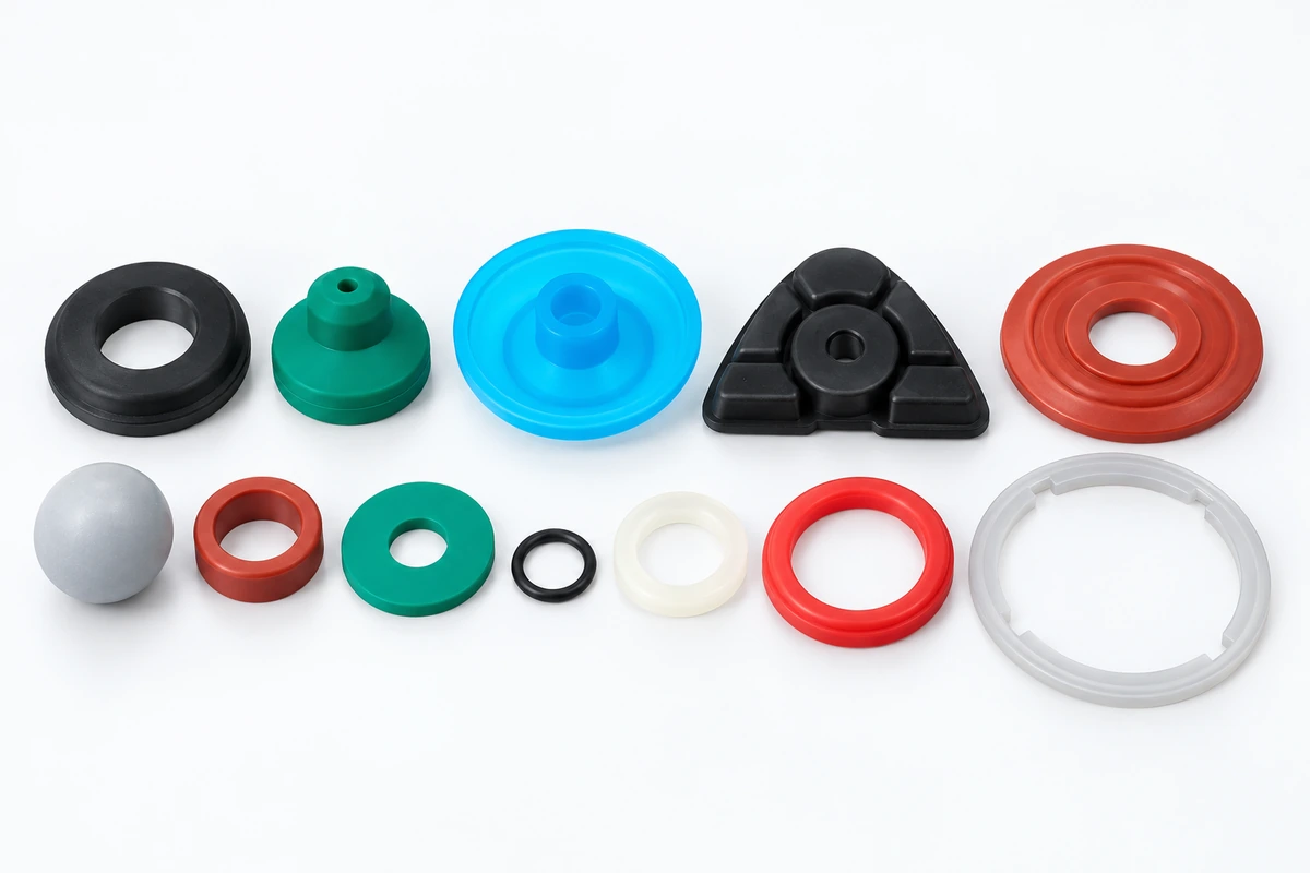
Seals & Enclosure Interfaces
For enclosure and panel interfaces, define the opening, seating surfaces and compressed geometry. Seals and molded interface parts need an agreed fit and evaluation method; a part photograph does not establish a sealing rating.
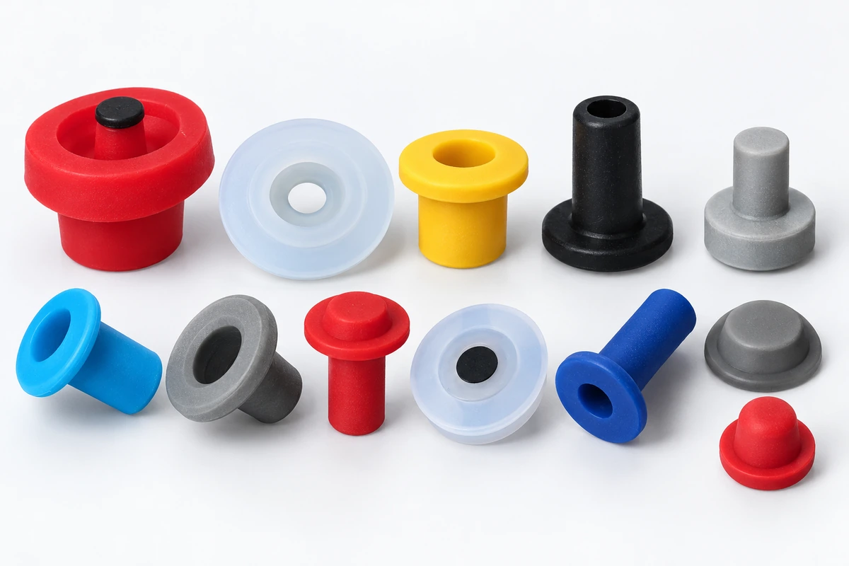
Grommets & Pass-Through Locations
For cable and pass-through locations, review the panel opening, panel thickness, cable dimensions and installation direction together. Grommets and bushing-style parts must be assessed against the surrounding geometry.
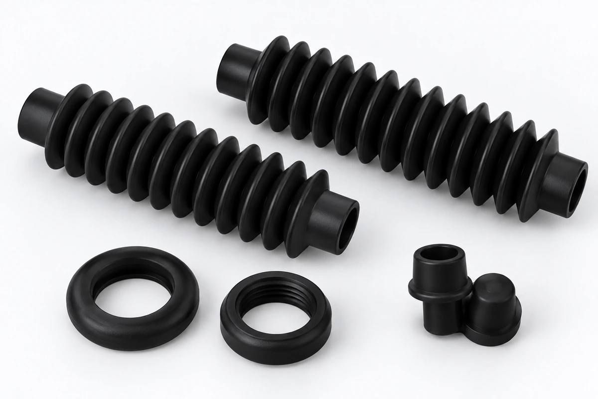
Bellows & Flexible Connections
For moving connections, define attachment features, compressed and extended positions and nearby obstructions. Bellows and boots need review across the movement envelope, not only in their free state.
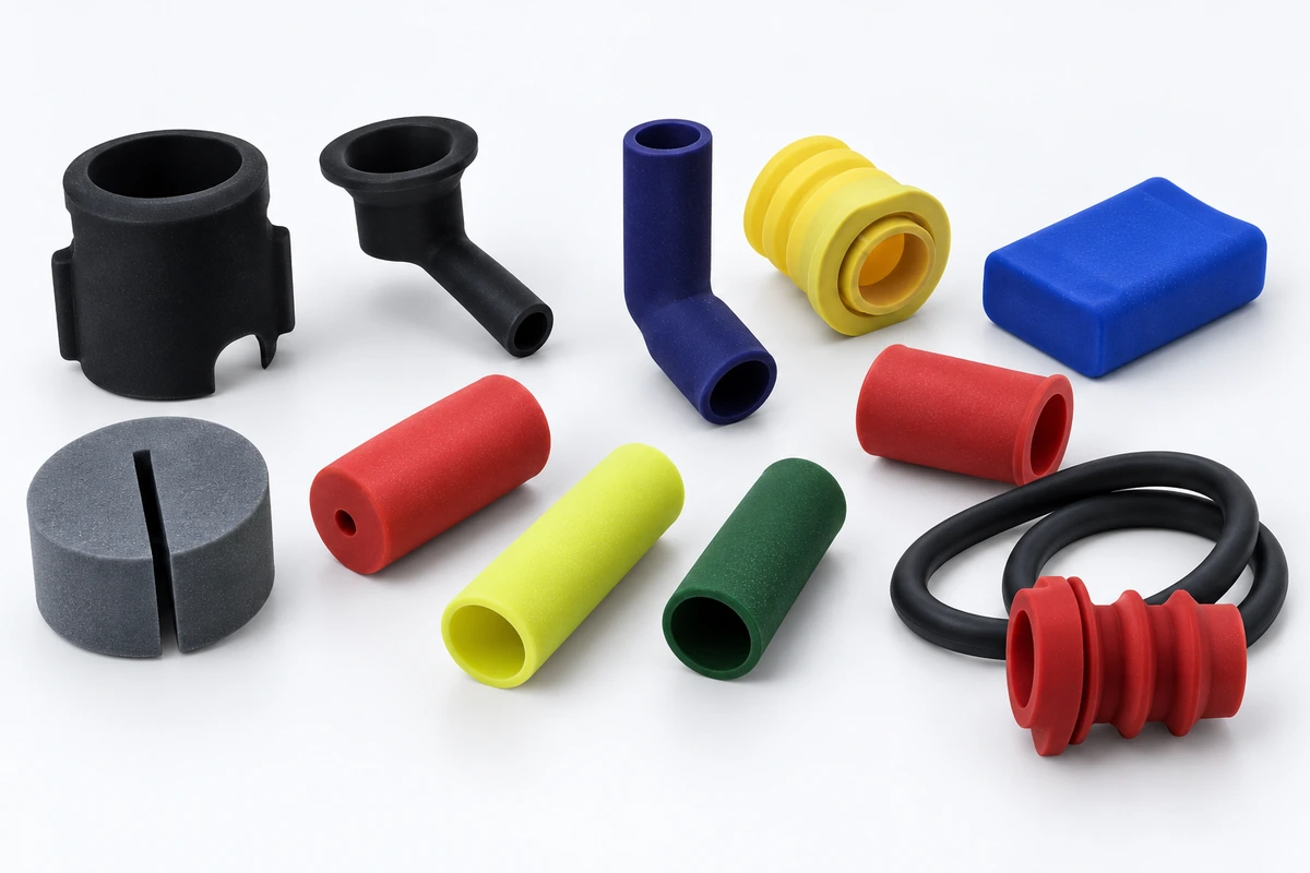
Sleeves & Contact Points
For sleeves and molded contact parts, identify the surfaces they touch, retention features and available space. State any load, deformation or repeated-contact requirements so the intended function can be evaluated.
Assembly, Material and Operating Requirements
A drawing defines the part. Assembly references and operating conditions help identify what needs review before tooling, material selection and sample acceptance are agreed.
Mating Geometry
Provide seating surfaces, holes, grooves and attachment features. The review should identify which interfaces control fit and where drawing dimensions or tolerance priorities need clarification.
Installation & Access
Show the assembly sequence, installation access and any temporary stretching or compression. Review both the route into position and the final fit to avoid treating these as the same requirement.
Movement & Clearance
Show compressed and extended positions alongside surrounding clearance. Define where contact is intended and where interference must be avoided, including the method used to evaluate movement.
Material & Service Conditions
Identify exposure, temperature, cleaning and repeated motion, together with any buyer-specified material or hardness target. Silicone is not suitable for every environment; agree material requirements and validation needs before committing to a design.
Find the Relevant Component Range
Use these product pages to review the relevant component range. Return with the part reference and its equipment context so the project is not assessed by appearance alone.
Industrial Silicone Parts
Explore seals, grommets, bushings, bellows, boots and other custom molded component directions.
Silicone Keypads & Buttons
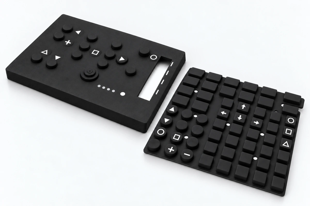
For equipment with user-facing controls, review the keypad or button together with panel geometry, markings and neighboring components.
From Your Project Brief to an Agreed Review Scope
Send the information you already have. Use the review to clarify open requirements and agree the tooling, sample and quotation scope before work proceeds.
Part & Assembly Files
Send a revision-marked 2D drawing, CAD file or physical sample with mating-part references. Use these to clarify the component geometry, assembly interfaces and missing dimensions.
Function & Use Conditions
Describe the component role, installation, movement and exposure. Use this information to define the material requirements and the application checks that still need agreement.
Critical Requirements
Identify fit dimensions, tolerance priorities, appearance and required documents. Agree which sample checks are needed, who performs them and what records will support acceptance.
Commercial Context
Share estimated quantities, project stage, target schedule and sampling expectations. Confirm quotation assumptions, tooling scope and charges, ownership, storage and any confidentiality requirements before sharing restricted files or ordering tooling.
Sample Evaluation Before Production
Agree the sample configuration and acceptance criteria before tooling decisions are finalized. The next stage should be based on the approved drawing revision and the checks agreed for the project.
Fit in the Intended Assembly
Identify the mating parts or fixture needed to assess installation, seating and alignment.
Critical Dimensions & Appearance
Mark the dimensions, visible surfaces and finish requirements that need to be checked against the approved reference.
Functional Evaluation
Define any required movement, sealing, load or environmental evaluation, including the method and acceptance criteria. Agree who performs each check and what records are required.
Application performance is project-specific. A product-family example is not evidence that a particular design meets an equipment requirement.
Connect Equipment Requirements to the Manufacturing Route
SM’s documented manufacturing scope includes tooling, silicone compression molding, surface finishing, assembly and inspection. The component requirements determine which steps are relevant; confirm the actual project scope rather than assuming every process is needed.
Tooling Review
Review molded geometry, important interfaces and drawing revision together. Confirm the tooling scope and any unresolved design information before the tooling stage.
Silicone Molding
Confirm the agreed material, part geometry and silicone molding route. Any markings or secondary work should be included in the defined scope where applicable.
Sample & Inspection
Review samples against agreed dimensions, appearance and assembly requirements. Confirm responsibility for any application-specific tests and the records required for approval.
Questions About Silicone Components for Industrial Equipment
Can we start with an existing part or assembly sample?
Is silicone suitable for every equipment application?
What matters most for a moving boot or bellows?
Can SM confirm a tolerance or performance target from a photograph?
What should procurement clarify before ordering tooling?
What happens if the drawing changes after quotation or sample review?
How should sample approval be defined?
YOUR EQUIPMENT COMPONENT PROJECT
Share the Part and the Assembly Around It
Send your drawing, CAD file or sample with the mating geometry, intended function, service conditions and quantity context. SM can review the available information and the next project steps.