SILICONE KEYPADS & BUTTONS
Custom Silicone Rubber Keypads & Buttons
SM manufactures custom silicone rubber keypads, molded buttons and button-mat components for electronic controls, handheld products and product-specific interfaces. Send a drawing, CAD file, existing sample or keypad reference to start the project review.
Custom Layouts • Molded Buttons • Printed Legends • Drawing- & Sample-Led Projects
PRODUCT DIRECTIONS
Custom Keypad & Button Components Built Around Your Interface
Start with the component type that best matches your product. The final structure is then defined around layout, geometry, visible surfaces and the surrounding interface.
01
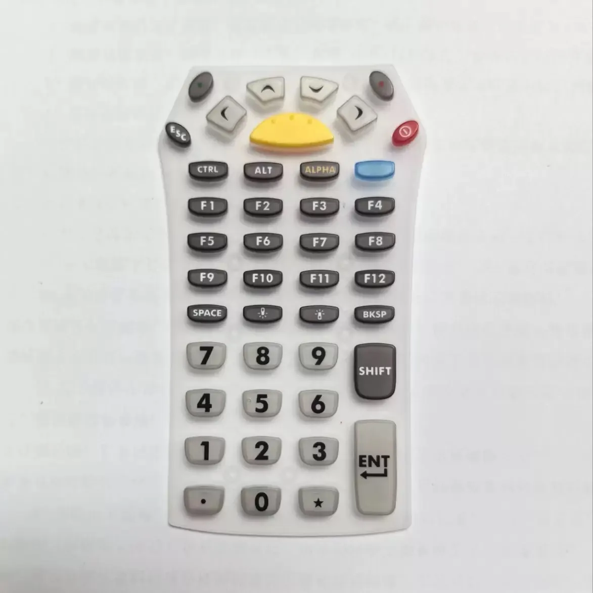
Custom Silicone Rubber Keypads
Multi-key molded silicone components developed around the required key layout, overall geometry and interface dimensions.
02
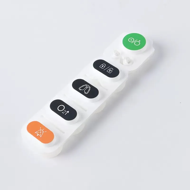
Molded Silicone Buttons & Button Mats
Individual, grouped or connected button structures for product-specific control layouts and user-input areas.
03
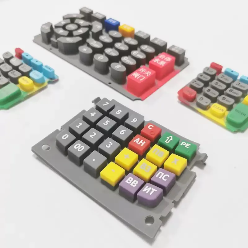
Printed & Marked Keypads
User-facing keypad components where approved legends, symbols, colors or graphic areas form part of the visible interface.
04
Handheld & Remote-Control Keypad Components
Compact keypad and button structures developed around handheld layouts and the surrounding enclosure.
05
Drawing- or Sample-Led Custom Structures
For unusual geometries or existing parts, start from the drawing, CAD model, physical sample or assembled-product reference.
COMMON APPLICATIONS
Common Product Contexts for Silicone Keypads & Buttons
Silicone keypads and molded buttons can be developed for different products while sharing the same core review points: layout, housing fit, visible markings, geometry and project-specific acceptance requirements.
01
Remote Controls
Compact keypad and button components developed around handheld layouts, enclosure fit, legends and user-facing control areas.
02
Industrial Controls & HMI
Keypads and control-interface components reviewed around panel fit, key layout, visible markings and the surrounding equipment interface.
03
Consumer Electronics
Silicone and related interface components developed around compact housings, visible appearance, control layout and assembled-product fit.
04
Home Appliances & Smart Home Controls
On-device keypads and buttons reviewed around front-panel geometry, symbols, color areas and the relationship with the housing.
05
POS Terminals & Access Control Equipment
Numeric and function-key interfaces developed around keypad layout, legends, enclosure fit and project-specific inspection priorities.
KEYPAD DEFINITION
Define the Keypad Around the Product Interface
The same product category can lead to very different keypad structures. The first review should define how the keys are arranged, what the user sees and how the silicone component relates to the surrounding product.
Key Layout
Define key count, spacing, grouping and the overall control arrangement.
Button Geometry
Review key shapes, molded features, openings and local geometry that affect the part.
Color & Visual Design
Identify visible color areas, grouped controls and appearance requirements.
Legends & Graphics
Provide approved symbols, text or artwork that needs to appear on the finished interface.
Contact / Switch Concept
Provide the intended contact or switch relationship as a project input where it affects component structure.
Housing / Enclosure Relationship
Show how the keypad sits in the enclosure or aligns with neighboring components.
ENGINEERING INPUTS
Identify the Dimensions & Interfaces That Matter Before Tooling
Tooling decisions should be based on the dimensions, interfaces and acceptance priorities that control the finished component.
01
Overall & Critical Dimensions
Provide overall size and identify the dimensions that matter most to fit or function.
02
Openings & Molded Features
Define holes, walls, ribs, local shapes and other molded features where relevant.
03
Mating & Alignment
Show how the keypad relates to the housing, PCB, supports or neighboring parts.
04
Tolerance Priorities
Identify the dimensions that need the closest project attention rather than assuming one tolerance applies everywhere.
05
Material / Hardness Target
If your project already specifies a material or hardness target, include it as a buyer-defined input for review.
06
Appearance & Inspection Priorities
Define the visible surfaces, color areas and inspection points that matter most to acceptance.
Project note: Tactile response, electrical properties, lifecycle, environmental protection and other functional targets are project-specific requirements and must be defined and confirmed for the individual design.
VISIBLE INTERFACE
Coordinate Legends & Graphics With the Molded Key Structure
The visible interface should be reviewed together with the molded geometry. Where the project requires it, SM can review suitable finishing routes against the actual keypad design and approved artwork.
01
Printed Legends
Text, symbols or graphic areas positioned around the molded key structure.
02
Laser-Processed Markings
Project-specific legends or surface details reviewed against the component design.
03
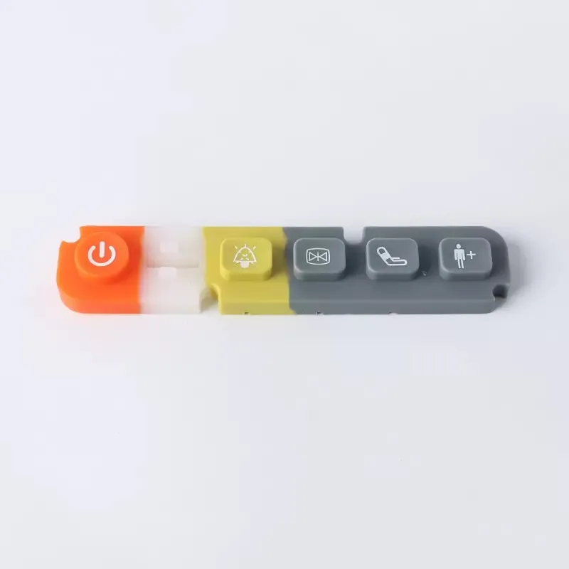
Multi-Color Visible Areas
Color changes and grouped control areas coordinated with the intended product appearance.
04
Project-Specific Surface Finishing
Additional finishing requirements can be reviewed where the keypad geometry and appearance support the process.
FROM FILES TO COMPONENT
Turn the Keypad Design Into a Manufacturable Part
01
Design / Sample Review
Start from a 2D drawing, 3D / STEP file, existing sample or product reference.
02
Interface & DFM Review
Review the layout, molded geometry, housing relationship and the requirements that affect the part.
03
Tooling & Keypad Sample
Define the tooling route and prepare the keypad sample around the approved component requirements.
04
Legends & Finishing
Apply the approved visual markings or project-specific finishing route where required.
05
Fit, Appearance & Project-Specific Checks
Review the finished keypad against the agreed dimensions, appearance and project-specific inspection points.


Real SM Manufacturing Context
Verified SM manufacturing media connects the keypad project to real tooling, molding, finishing and inspection work.
WHAT TO SEND
Give Us the Information That Defines the Keypad
You do not need every detail finalized before the first review. Send what you already have and identify the requirements that matter most.
01
Component Files
2D drawing • 3D / STEP file • physical sample • existing keypad reference
02
Layout & Geometry
Overall dimensions • key count • spacing • openings • key / button shapes
03
Product Relationship
Housing reference • mating parts • assembled-product image or sample
04
Visible Requirements
Legends • symbols • colors • artwork • user-facing surfaces
05
Functional Inputs
Buyer-defined contact method • tactile / performance targets • environmental requirements where relevant
06
Critical Dimensions & Tolerance Priorities
Identify the dimensions that are most important to fit, movement or assembly.
07
Material / Hardness Target
Include the target if already specified by your engineering or product team.
08
Project Context
Estimated quantity • target timing • inspection priorities • required documents
KEYPAD PROJECT FAQ
Questions About Custom Silicone Rubber Keypads & Buttons
Can SM make a custom silicone keypad from my drawing or CAD file?
Can I send an existing keypad or button sample instead of a drawing?
Can key legends, symbols and colors be customized?
What should I provide about the housing or surrounding product?
What functional requirements should I provide for a keypad project?
How do I start a keypad quotation?
YOUR NEXT KEYPAD PROJECT
Send Your Silicone Keypad or Button Project for Review
Share the drawing, CAD file, sample or existing keypad reference. Include the layout, housing relationship, visible markings, critical dimensions and project requirements you already know, and SM can review the next manufacturing steps.